Figure 1: Multiphase charging algorithm can avoid battery overload or overheating. The charger can be connected to the battery at any time
Dry batteries are used in many mobile and handheld devices, but applications such as tools require more energy and lighter solutions. Nickel cadmium batteries have higher power density and current capacity, and have been provided in the form of existing dry batteries. But the charging current is limited to around C/5 or C/10 (C=nominal capacity, in Ah), which takes 10 hours or more. In theory, they provide more charging cycles, but the memory effect often shortens the lifespan. The self discharge rate is 10-20% per month.
Dry batteries are used in many mobile and handheld devices, but applications such as tools require more energy and lighter solutions. Nickel cadmium batteries have higher power density and current capacity, and have been provided in the form of existing dry batteries. But the charging current is limited to around C/5 or C/10 (C=nominal capacity, in Ah), which takes 10 hours or more. In theory, they provide more charging cycles, but the memory effect often shortens the lifespan. The self discharge rate is 10-20% per month.
Cadmium is toxic and was banned in many countries many years ago and replaced by nickel hydrogen batteries. They are sturdy and durable, and are more resistant to overcharging or deep discharge. The memory effect and self discharge are significantly lower, but still not ideal for mobile devices. Fast charging within a few hours requires more complex chargers.
Lithium ion batteries provide higher energy density, with a monthly self discharge rate of only 1-2% and no memory effect. They can also withstand a wider range of environmental temperatures, making them an ideal solution for mobile phones and laptops. Nowadays, they have become the preferred choice for many applications.
Lithium ion batteries provide higher energy density, with a monthly self discharge rate of only 1-2% and no memory effect. They can also withstand a wider range of environmental temperatures, making them an ideal solution for mobile phones and laptops. Nowadays, they have become the preferred choice for many applications.
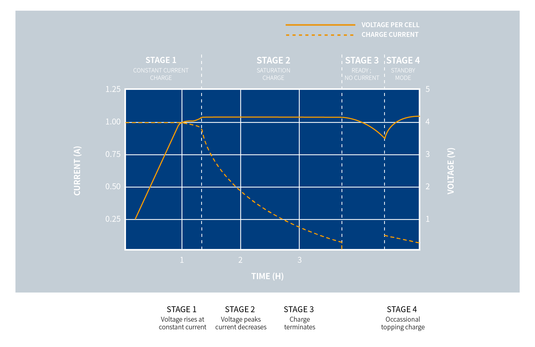
Fast charging can be performed at a rate of 0.5C to 1C, but with different phases (Figure 2).

Figure 2: Typical charging stages of lithium-ion batteries
Lithium can catch fire and there are issues with mining. Researched battery topology structures based on other less hazardous and easily exploitable materials, and provided different energy densities, faster charging speeds, or lower costs. They all have one thing in common, which is that managing the charging process and monitoring the status of each battery is crucial for safety and longevity.
For decades, measuring the state of charge (SoC) of batteries has been a major challenge. For lead-acid batteries, the voltage and charging curve are somewhat accurate, but for other battery materials, the discharge curve is quite flat (Figure 3). The value also depends on the technology, number of charging cycles, and battery life.

Figure 3: Typical voltage and discharge curves for different battery topologies
It is complex to measure the current during the charging and discharging stages using analog circuits, but it is easy to use microcontrollers and current sensors. Through this process called Coulomb counting, SoC can be calculated, and the equation can include battery loss, aging, self discharge, and temperature.
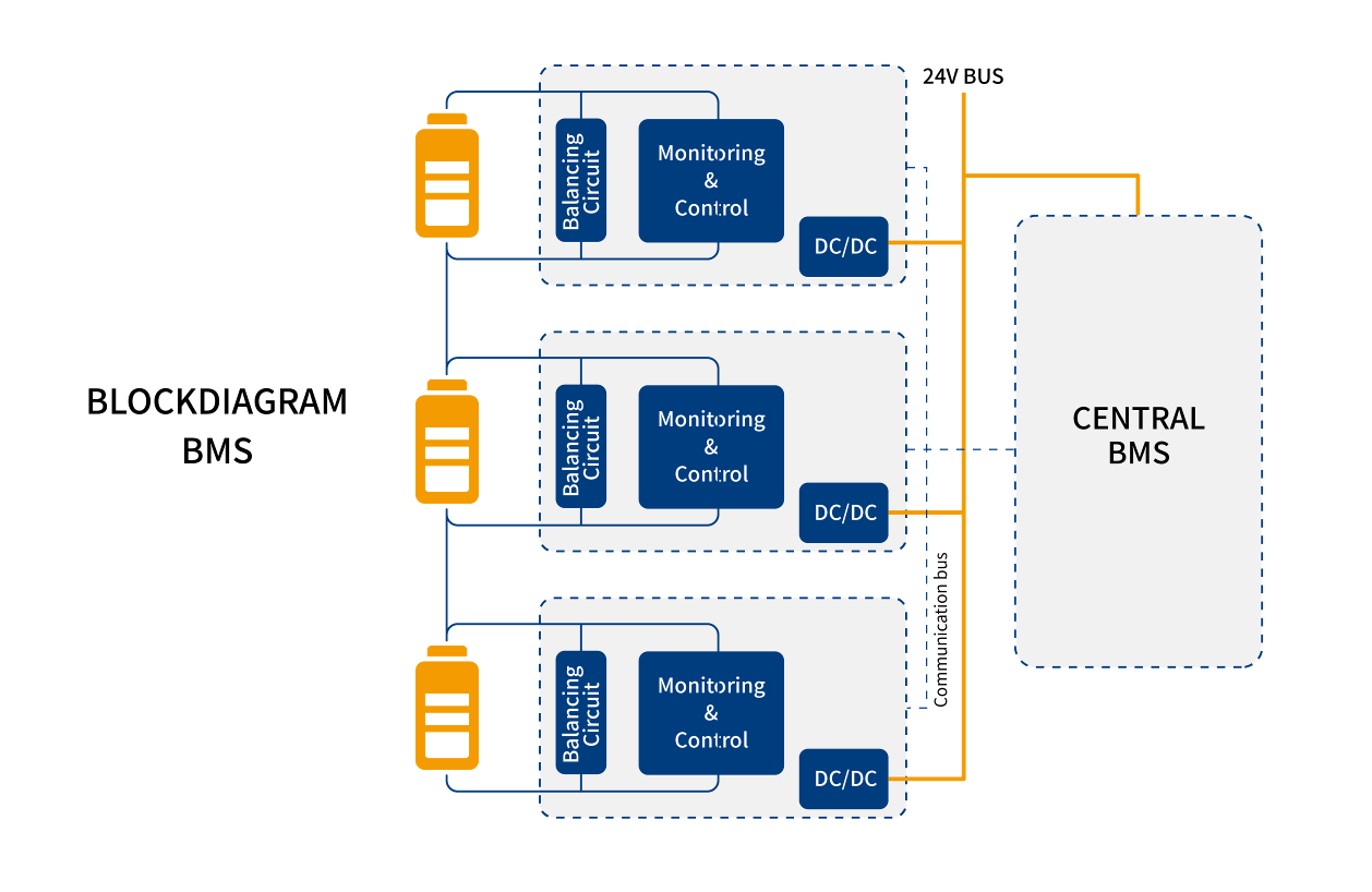
The Battery Management System (BMS) monitors the battery status and avoids any operations outside the safe operating area. They control the charging process, balance the energy stored in each battery, monitor key data such as charging status and temperature, and report any abnormal situations. Figure 4 shows a simplified block diagram of the BMS system

Figure 4: Each battery or battery block in the array is monitored and controlled, and data is sent to the central battery management system
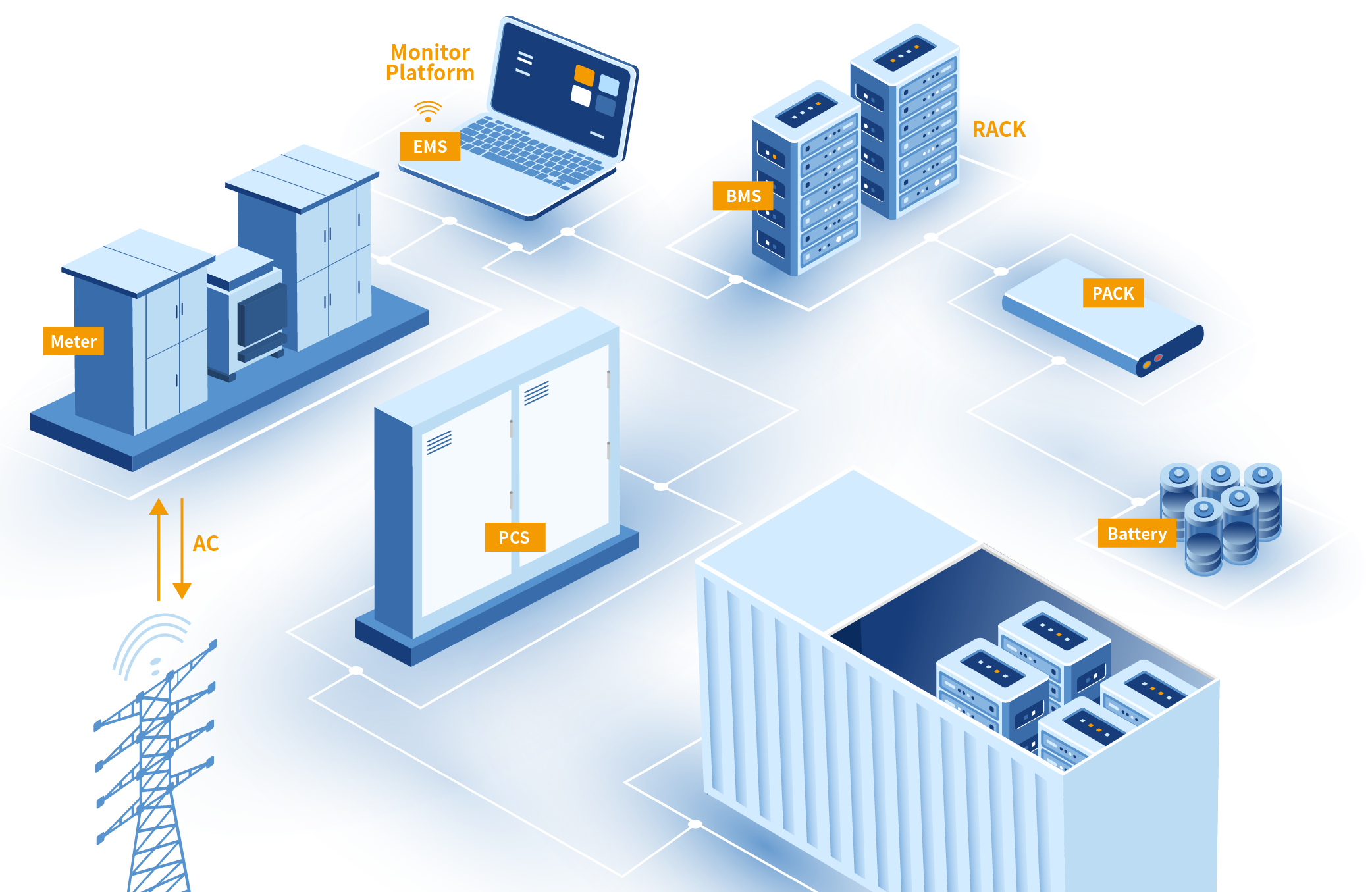
Monitoring several batteries is easy in low-power applications, but it is a real challenge in large arrays with hundreds of kWh or several MWh, as well as a large number of series and parallel connected batteries. These devices (Figure 5) are used to store surplus from renewable energy parks, balance the AC power grid, or act as UPS (uninterruptible power supply) critical devices.
Monitoring several batteries is easy in low-power applications, but it is a real challenge in large arrays with hundreds of kWh or several MWh, as well as a large number of series and parallel connected batteries. These devices (Figure 5) are used to store surplus from renewable energy parks, balance the AC power grid, or act as UPS (uninterruptible power supply) critical devices.

Figure 5: Large scale energy storage system with battery management system
As shown in Figure 4, each battery must be monitored, and the circuit requires a separate isolated power supply voltage generated by a 12V or 24V bus. It sounds like a simple design challenge that can be solved through low-power, standard converter modules.
But for high-power applications with hundreds of series connected batteries, the voltage of the entire battery pack can reach 600-800 volts, and isolation needs to be strengthened. Most 24Vin DC/DC power converters are designed for typical industrial applications that require 500V or 1600V isolation voltage.
To avoid degradation and failure of isolation materials, it is allowed to continuously apply a working voltage much lower than the isolation voltage, as defined by safety standards (Figure 6). These values also depend on the application type and environmental conditions.

Figure 6: Typical isolation voltage for industrial applications
A battery pack with 600-800Vdc requires an enhanced isolation barrier of 3000Vac (or 4243Vdc) to be installed in the DC/DC power converter, which is too high for many standard converters with only 1600V isolation. But does a converter with 3kVac isolation really meet the requirements?
These large battery systems are connected to the AC power grid, located near wind turbines, solar parks, or substations. They are exposed to high transients and should meet the requirements of OVC III (overvoltage category III), which requires a 400Vac three-phase power supply with 4kV isolation voltage.
Although these OVC categories are designed for AC applications, they help find solutions for DC batteries. Unfortunately, when searching for industrial DC/DC power converters with 4kVac isolation on manufacturer websites, there are usually no matching items
However, in some markets, the highest isolation barrier is crucial. Patients connected to medical devices must be protected from any electric shock, so the market has very strict requirements for isolation and leakage current.
Medical standards define different means of patient protection (MOP) and operator (MOOP). Devices connected to patients and invasive systems must meet 2 MOPPs (two types of patient protection measures) and an isolation voltage of 4kVac. The converter specified for this standard can be used for the above-mentioned BMS system.
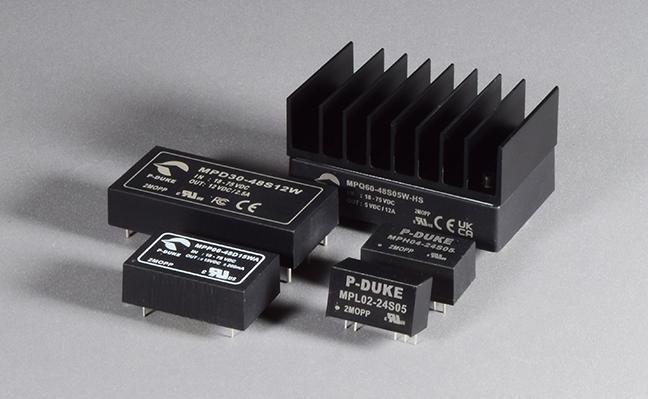
P-DUKE has various DC/DC power converters that can meet these 2MOPP requirements and provide a higher 5kVac isolation voltage. The complete product line with power levels ranging from 1W to 60W offers single and dual outputs. With various input voltage ranges from 5V to 75V, they can be deployed in all different applications. It is easy to find suitable solutions using the product search function on the P-DUKE website.

Figure 7: P-DUKE has a very comprehensive medical grade DC/DC power converter with single and dual outputs, with power levels ranging from 1W to 60W
For example, MPD30-24S12W is a 30W converter with 9-36 inputs and 12V outputs that can create separate isolated power supply voltages for BMS circuits connected to batteries or battery arrays from a 12V or 24V bus.
Medical standards also require leakage current to be within the microampere range and a creepage distance of 8mm. This is the shortest distance along the isolation material between the input and output inside the converter. Similar to capacitors, the isolation material (ε 0) and thickness (d) inside the converter define the capacitance from input to output:

The thicker the material and the wider the distance, the lower the capacitance between the input and output. Although using one or two converters in the system is not important, it becomes an important factor when combining hundreds of converters of different voltage levels in a large BMS system. AC voltage, transients, and noise can couple across these isolation gates. It not only interferes with highly sensitive measurement or communication equipment, but also causes high and dangerous leakage currents in high-voltage AC power sources.
Let’s compare a practical example. The isolation capacitor of P-DUKE’s medical converter MPD30 is only 20pF. Even for a sensor signal of 1MHz, this means a high impedance of 8k Ω. The isolation capacitor of standard industrial converters can exceed 1500pf. This is 75 times higher, and the impedance of a 1MHz signal drops to only 107 Ω. When many converters are connected in parallel, the total capacitance and impedance can reach the critical value of noise coupling, as well as the critical value of AC leakage current across these gates.
In an application with 100 medical grade converters and a total capacitance of only 2nF, according to the formula I=U * 2 * π * f * C, the leakage current in a 400V/50Hz application is only 0.25 μ A.
When using an industrial grade converter, the total capacitance is 150nF, and the leakage current will increase to around 19mA. Although not yet fatal, it can cause severe electric shock. Along with the leakage current of other devices in the system, a 35mA RCD circuit breaker (residual current circuit breaker) can be tripped.
Like medical applications, reliability is another important factor in battery storage systems. The MPD30 power converter series from P-DUKE is designed for maximum reliability, with an MTBF value greater than 1 million hours (MIL-HDBK-217F at full load). P-DUKE also provides a 5-year product warranty for these medical devices, which is much longer than the 2-year warranty offered by many other converter manufacturers.
Have you ever thought about why we call medical power converters for health batteries? A highly complex BMS system is required to ensure the safe and long-lasting operation of such a large battery pack. These applications are challenging, but with P-DUKE’s medical power converter and powerful technical support, they can be solved to ensure healthy operation and long lifespan.


Leave a comment
Your email address will not be published. Required fields are marked *