ABB FS450R12KE3/AGDR-71C | IGBT Module + Gate Driver Assembly – 450A, 1200V
1. Combined Assembly Overview
The ABB FS450R12KE3/AGDR-71C is not a single component but a factory-matched assembly consisting of two separate but interdependent parts:
| Component |
Description |
ABB Part Number |
| FS450R12KE3 |
IGBT module – 450A, 1200V, six-pack (3-phase inverter) |
FS450R12KE3 |
| AGDR-71C |
Gate driver board – dual-channel, isolated, with desaturation protection |
AGDR-71C |
These two components are sold together as a matched set because the AGDR-71C gate driver is specifically calibrated and programmed for the FS450R12KE3 IGBT module's characteristics (gate charge, input capacitance, desaturation threshold). Using a different gate driver with this IGBT module, or using this gate driver with a different IGBT module, will result in unreliable switching, increased losses, or catastrophic failure.
Typical Application Context: This assembly is found in ABB's high-power industrial drives, including the ACS800-107 (regenerative supply modules), ACS800-207 (IGBT supply units), and wind turbine converters. The FS450R12KE3 is a sixth-generation (NPT-Trench) IGBT module, while the AGDR-71C is a current-sourced gate driver with advanced protection features.
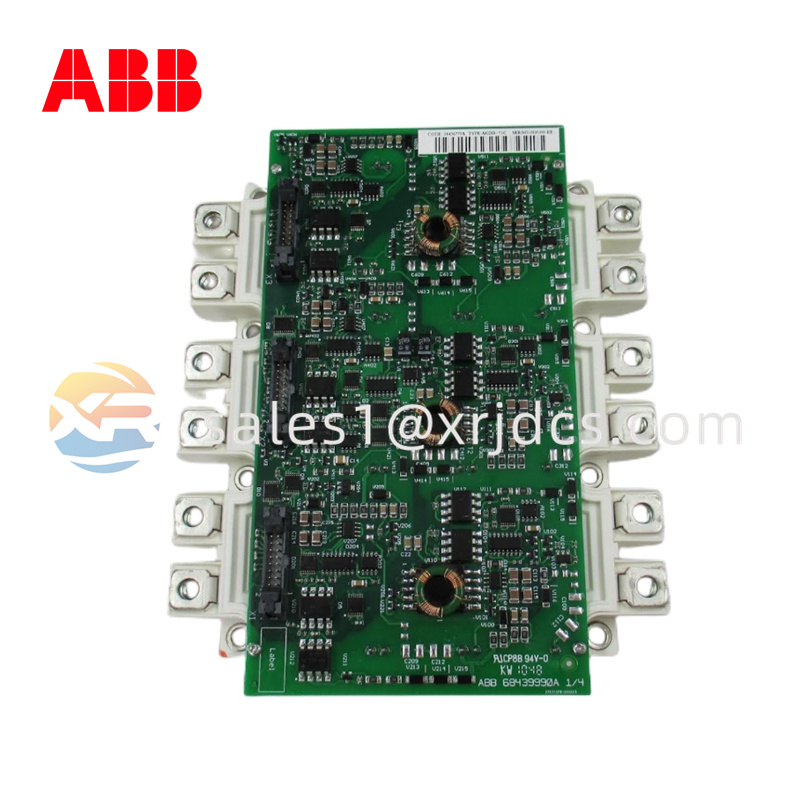
2. Component B: AGDR-71C – Gate Driver Board
2.1 Product Overview
The AGDR-71C is a dual-channel, isolated gate driver board designed specifically for driving two IGBTs (typically one phase leg: high-side and low-side) of the FS450R12KE3 module. Multiple AGDR-71C boards are used to drive all six IGBTs in a three-phase inverter – typically three boards (one per phase leg) or two boards (with one board driving two phase legs – check drive specific configuration).
The board incorporates:
-
Galvanic isolation (pulse transformers) between the low-voltage control side and high-voltage IGBT side – 4000Vrms withstand
-
Desaturation (Desat) detection for short-circuit protection (response time <2µs)
-
Active clamping (overvoltage suppression) during turn-off
-
Two-level turn-off (soft shutdown) to reduce voltage spikes during fault conditions
-
Under-voltage lockout (UVLO) on both +15V and -15V supplies
-
Status feedback (fault output) to the drive's main control board
The "-C" revision indicates improved noise immunity and lower propagation delay (250ns vs. 350ns on the -B revision).
2.2 Technical Parameters (AGDR-71C) – Table Format
| Parameter |
Specification |
| Input Supply |
|
| Supply voltage (VDD) |
+15V DC ±5% (14.25–15.75V) |
| Supply current (IDD) |
150 mA typical (no load), 350 mA peak per channel |
| Negative supply (VEE) |
–15V DC ±5% (14.25–15.75V) |
| Supply current (IEE) |
50 mA typical |
| Output (Gate Drive) |
|
| Peak output current |
±10A (sink/source) |
| Output voltage (high-side) |
+15V / –8V (relative to emitter) |
| Output voltage (low-side) |
+15V / –8V (relative to emitter) |
| Gate resistance (internal) |
1.2Ω (external resistor can be added) |
| Maximum switching frequency |
8 kHz (typical for 450A IGBT) |
| Protection |
|
| Desaturation detection voltage |
7.0V ±0.5V (VCE threshold) |
| Desat blanking time |
3 µs (fixed) |
| UVLO threshold (positive supply) |
12.5V ±0.5V (turn-off below) |
| UVLO threshold (negative supply) |
–11.0V ±0.5V (turn-off above) |
| Fault output |
Open-collector, 5mA max, active low |
| Timing |
|
| Propagation delay (input to output) |
250 ns typical |
| Desat response time |
1.5 µs typical (from fault to gate turn-off) |
| Minimum pulse width |
1 µs |
| Isolation |
|
| Isolation voltage (input to output) |
4000 Vrms (1 minute) |
| Common mode transient immunity (CMTI) |
50 kV/µs |
| Physical |
|
| Dimensions (L x W) |
95 x 55 mm |
| Thickness |
18 mm (including standoffs) |
| Weight |
0.08 kg (0.18 lb) |
| Connectors |
10-pin control input (IDC), 4-pin gate output (Molex), 2-pin DC link sense |
| Mounting |
4 x M3 standoffs (torque 0.6 Nm) |
| Operating temperature |
–40°C to +85°C |

3. Electrical Integration & Wiring
Connection Between AGDR-71C and FS450R12KE3 (per phase leg):
| AGDR-71C Connector |
Pin |
Signal |
FS450R12KE3 Terminal |
Notes |
| X1 (Gate output) |
1 |
High-side gate |
G_U (or G_V, G_W) |
Use twisted pair |
| X1 |
2 |
High-side emitter |
E_U (or E_V, E_W) |
|
| X1 |
3 |
Low-side gate |
G_X, G_Y, G_Z (lower IGBTs) |
|
| X1 |
4 |
Low-side emitter |
E_X, E_Y, E_Z (common DC-? No) |
|
| X3 (DC link sense) |
1 |
DC+ voltage sense |
DC+ terminal (positive bus) |
Through 1MΩ divider |
| X3 |
2 |
DC- voltage sense |
DC- terminal (negative bus) |
|
Control Inputs (10-pin IDC connector X2):
| Pin |
Signal |
Description |
| 1 |
+15V |
Positive supply for driver logic |
| 2 |
+15V return |
Common (0V) |
| 3 |
-15V |
Negative supply |
| 4 |
-15V return |
Common (0V) |
| 5 |
Input H |
PWM input for high-side IGBT (active high) |
| 6 |
Input L |
PWM input for low-side IGBT (active high) |
| 7 |
Fault H |
Fault output (open collector, active low) for high-side |
| 8 |
Fault L |
Fault output for low-side |
| 9 |
Reset |
Global reset (active high, >5µs pulse) |
| 10 |
Ground |
Signal ground (common with +15V return) |
Important Wiring Rules:
-
Gate resistors: The AGDR-71C has internal 1.2Ω gate resistance. For slower switching (to reduce EMI), add external resistors in series (0–10Ω, 1W). Do not reduce below 0.5Ω total – may cause oscillation.
-
Desat sensing: The AGDR-71C monitors VCE across the IGBT during the on-state. A high-voltage diode (included on the driver board) connects to the IGBT's collector. Ensure the sensing wire is short (<100mm) and twisted with the emitter wire.
-
DC link sensing: Required for active clamping and overvoltage protection. Connect X3 pins to DC+ and DC- through the drive's resistive divider network (typically 1MΩ / 10kΩ). Do not connect directly – the driver inputs are only 15V tolerant.
4. Protection Features & Fault Handling
Desaturation Protection (Short-Circuit):
When the IGBT is turned on, its collector-emitter voltage drops to VCE(sat) (~1.7V). If a short circuit occurs (output phase-to-phase or phase-to-ground), the current rises rapidly, and VCE increases to the full DC link voltage (600–800V). The AGDR-71C monitors VCE during a 3µs blanking time (to ignore switching transients). If VCE exceeds 7V after blanking, the driver immediately turns off the IGBT using two-level turn-off: first to a reduced gate voltage (approx. 8V) for 2µs, then fully off. This reduces voltage overshoot by 30–40% compared to abrupt turn-off.
Active Clamping:
During turn-off of a high current, parasitic inductance in the DC bus can cause voltage spikes exceeding the IGBT's 1200V rating. The AGDR-71C senses the collector voltage through a Zener diode network. If VCE exceeds 1100V, the driver partially turns the IGBT back on, dumping energy into the DC bus instead of allowing a destructive overvoltage.
Under-Voltage Lockout (UVLO):
If the +15V supply drops below 12.5V, the driver turns off the IGBTs (even if PWM inputs are active). When the supply recovers above 13.5V, normal operation resumes after a 10µs delay. The -15V supply has independent UVLO (threshold -11V).
Fault Reporting:
When a fault occurs (desat, UVLO, over-temperature sensed externally), the corresponding Fault pin (pin 7 or 8) pulls low. The drive's main control board must:
-
Detect the fault (interrupt or polling)
-
Disable PWM outputs to all phases (not just the faulted phase)
-
Wait at least 100µs
-
Assert a reset pulse (>5µs) on pin 9 to clear the fault latch
If the fault condition persists, the driver will re-trip immediately upon reset.
5. Testing & Verification
Before installing the assembly into a drive:
Test 1: Visual & Mechanical
-
Inspect FS450R12KE3 for cracked ceramic, damaged terminals, or bulging baseplate.
-
Inspect AGDR-71C for burnt components, cracked pulse transformers, or loose connectors.
-
Verify the gate driver's standoffs are not shorting to the IGBT's power terminals.
Test 2: IGBT Module Diode Check (power off)
-
Set multimeter to diode test.
-
Measure between C2E (collector to emitter) of each IGBT – should read OL (open) in forward direction (positive on collector) and 0.3–0.7V in reverse direction (positive on emitter) due to the freewheeling diode.
-
Measure gate to emitter – should read open circuit (>10 MΩ) in both directions (the gate is isolated by oxide).
Test 3: Gate Driver Output (low voltage, no DC bus)
-
Apply +15V and -15V to the AGDR-71C (pins 1 and 3).
-
Apply a 1 kHz, 50% duty cycle, 5V PWM signal to Input H (pin 5).
-
Measure between Gate H (X1 pin 1) and Emitter H (X1 pin 2) with an oscilloscope. You should see a 15V pulse (relative to emitter) rising from –8V (off) to +15V (on). The pulse shape should be clean with no ringing >2V.
Test 4: Desaturation Test (simulate fault)
-
With the IGBT module disconnected (gate and emitter open), apply +15V to the AGDR-71C and a continuous "ON" PWM signal.
-
The driver should detect desaturation (since VCE cannot be measured) and pull the Fault pin low within 5µs.
-
The output voltage between Gate and Emitter should drop to 0V (off).
6. Storage & Shelf Life
| Parameter |
Recommendation |
| Storage temperature |
0°C to +40°C (32°F to 104°F) |
| Humidity |
<60% non-condensing |
| ESD protection |
Always store in anti-static bag – the AGDR-71C's gate outputs are ESD-sensitive |
| Orientation |
Flat (FS450R12KE3) – do not stack heavy items on top (ceramic can crack) |
| Shelf life (unused) |
5 years (FS450R12KE3), 7 years (AGDR-71C) – after that, re-form capacitors and verify gate oxide |
| Re-forming procedure (after >3 years storage) |
Apply 25V DC through 100Ω resistor to DC+ and DC- (FS450R12KE3 not applicable – no capacitors inside). For AGDR-71C, apply +15V/-15V for 24 hours before use. |


 Switzerland